Table of Contents
Interfacing with the CUBLOC
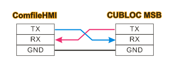
Connect the CUBLOC MSB Series Products
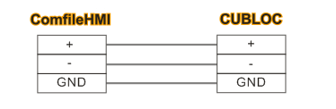
Connect the ComfileHMI's RS-232 port to the MSB's RS-232 port as illustrated below. (The CUBLOC's built-in Modbus slave can only be used on the CUBLOC's serial channel 1.)

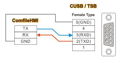
Connecting the CUBLOC CUSB Series Products
Connect the ComfileHMI's RS-232 port to the CUSB's RS-232 port as illustrated below.
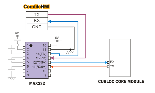
Connecting the CUBLOC Core Module
The CUBLOC's 5V-level serial port must first be connected to a level shifter like the MAX232 to match the ComfileHMI's +/- 12V-level serial port. Some CUBLOC core modules already have a MAX232 built-in.
ComfileHMI's Communication Settings
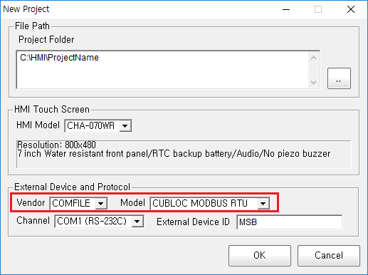
When creating a new project, select the COMFILE and CUBLOC MODBUS RTU protocols.
Connecting via RS-485
The ComfileHMI's RS-485 port can be connected to the CUBLOC's serial channel 1 through an RS-232 to RS-485 converter.
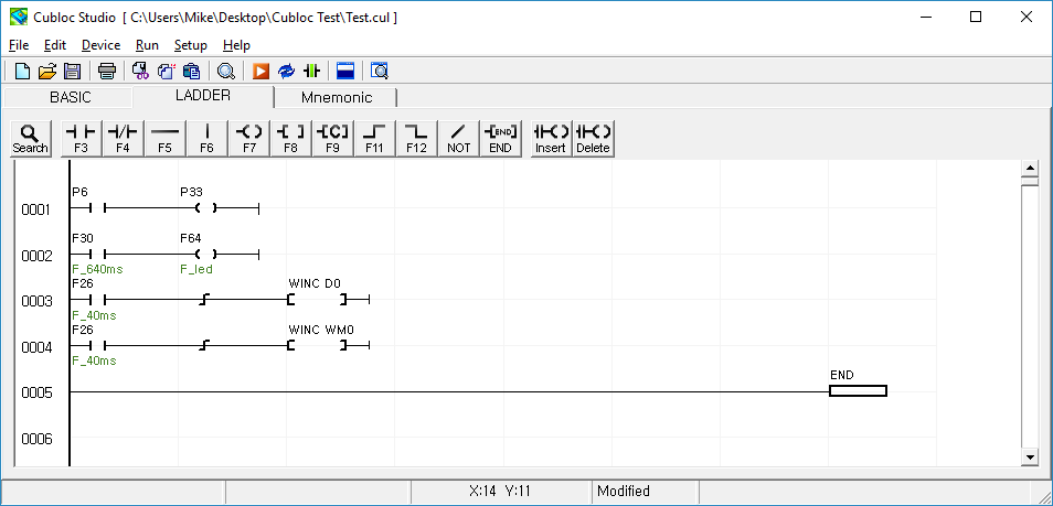
CUBLOC Source Code
Please use CUBLOC Studio v4.0 or later. The following source code is a minimal Modbus slave implementation.
#include "MSB6XX"              ' MSB6XX Series device declaration.
                               ' Core modules would use a declaration like Const Device = CB280
Opencom 1,115200,3,200,200     ' Channel 115200bps,8 data bits, no parity, 1 stop bit
Set Modbus 1,1,100             ' Modbus RTU, slave address 1, frame delay 100 (approx. 10mS)
Set Ladder On                  ' Start the ladder scan

Do                             ' Main loop
Loop
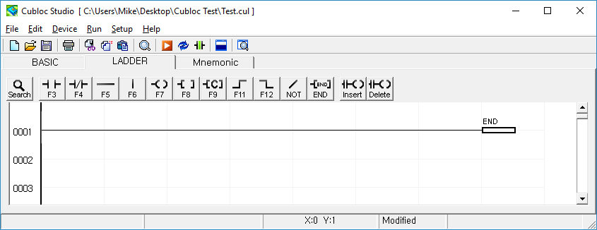
Ladder Logic must have at least one END rung.
<html> <!–
MSB Logic Settings
MSB Logic can be used to program the MSB Series solely in Ladder Logic, without BASIC programming.
- Cubloc Studio can be used to program CUBLOC-based devices in BASIC and/or Ladder Logic.
- MSB Logic can be used if only Ladder Logic is needed.
Configure the MSB as illustrated below.

115200 bps, no parity, 8 data bits, 1 stop bit, slave address 1
–>
</html>
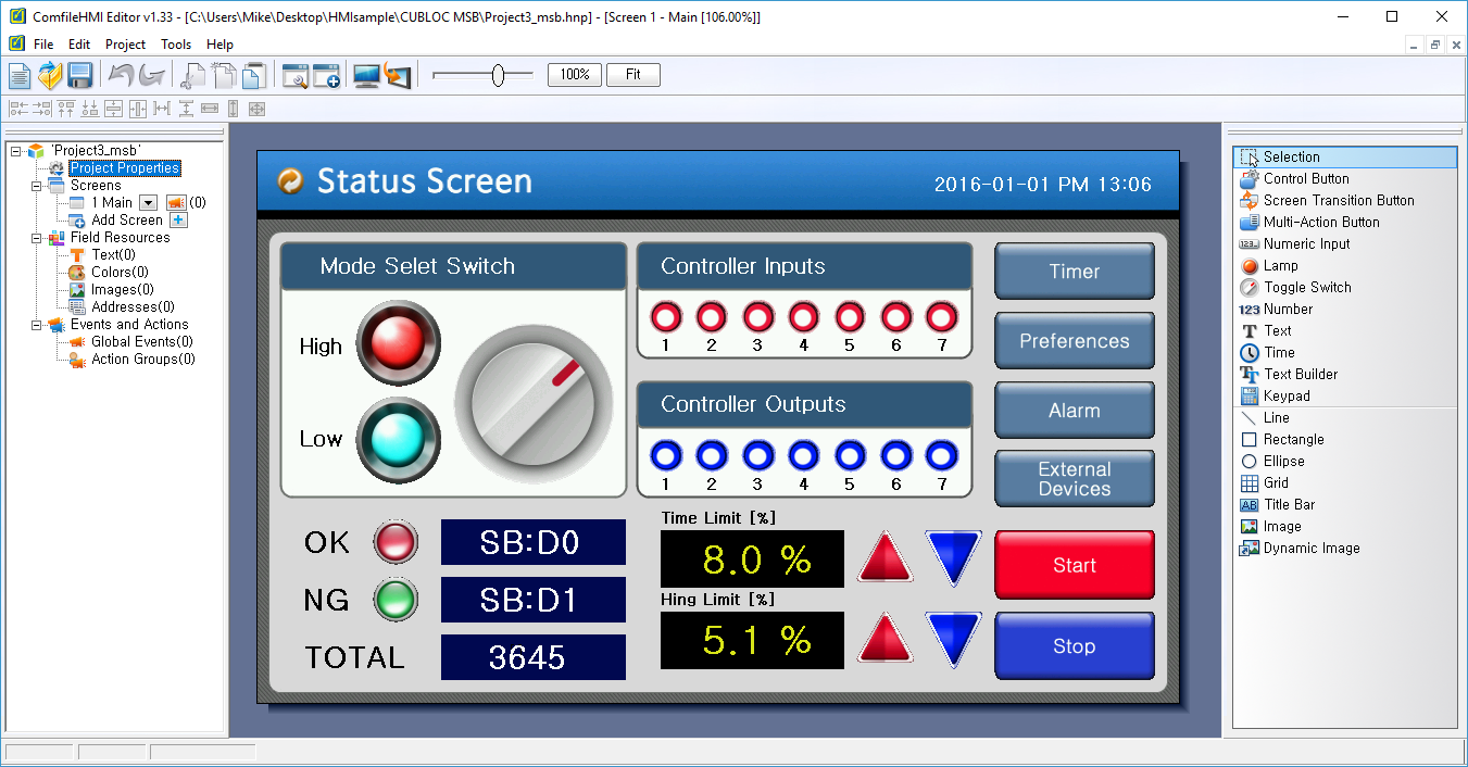
ComfileHMI Sample Project
ComfileHMI Sample Project ⇐ Download the ComfileHMI sample project
MSB Source Code ⇐ Download the Cubloc Studio/MSB Logic project files for the source code listed below.
#include "MSB6XX"
Opencom 1,115200,3,200,200
Set Modbus 1,1,100

Usepin 8,In
Usepin 20,In
Usepin 32,Out
Usepin 33,Out
Usepin 34,Out
Usepin 35,Out
Set Ladder On
Do
 Delay 1000
 Incr _D(1)
Loop
Accompanying Ladder Logic source.